Business License

Edge Drive Ball Mill Reducer: A Complete Selection Guide for Cement and Mining
An edge drive ball mill reducer sits beside the mill drum and transmits motor power to the pinion that meshes with the girth gear ring. For cement plants, mining operations, and raw meal grinding systems, this arrangement remains one of the most common drive layouts for mid-size and older mills. The right edge drive ball mill reducer keeps your mill running efficiently; the wrong one leads to vibration, premature tooth wear, and unplanned shutdowns.
What if the reducer currently on your mill was selected only for price, not for your actual duty cycle? Many plants discover this mistake only after the first failure. This guide explains how edge drive works, when it is the right choice, and how to select a reducer that matches your mill's torque, speed, and environmental demands.
You will learn the key differences between edge drive and center drive, the specifications that matter most, and why the MBY series is the industry-standard edge drive mill reducer. By the end, you will have a clear selection framework and a checklist for talking to suppliers.
Key Takeaways
Edge drive ball mill reducers are the right choice for many mid-size cement and mining mills because they are simpler to maintain and easier to retrofit than center drives.
The MBY series is the standard edge drive mill reducer for ball mills, raw meal mills, and coal mills in cement plants.
Required output torque, service factor (typically 1.5-2.5 for ball mills), and reduction ratio are the three most important selection inputs.
Case-hardened alloy steel gears (HRC 58-62), precision-ground tooth profiles, and rigid housings separate industrial-grade reducers from light-duty units.
Custom or non-standard edge drive reducers solve footprint, shaft, and load problems when a catalog model does not fit.
What Is an Edge Drive Ball Mill Reducer?
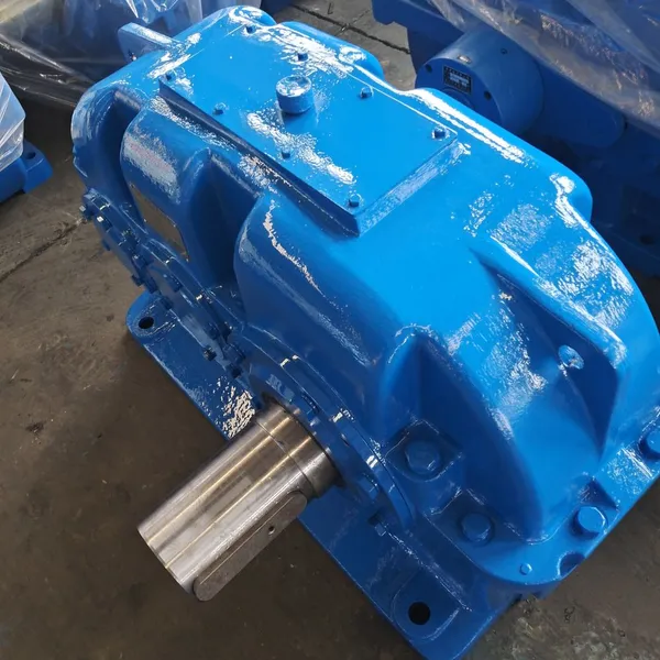
An edge drive ball mill reducer is a heavy-duty gear reducer that converts high-speed, low-torque motor power into the low-speed, high-torque rotation required by a ball mill drum. In this layout, the motor and reducer sit at the side of the mill. The reducer output shaft drives a small pinion gear, and the pinion meshes with a large girth gear ring bolted around the outside of the mill drum.
This side-mounted arrangement is common in:
Cement raw meal mills
Cement finish mills (also called a cement mill reducer application)
Coal mills
Slag grinding mills
Mining ball mills up to mid-size diameters
Some buyers also refer to the unit as a ball mill gearbox, especially when describing the complete drive assembly that includes the reducer, pinion, and girth gear ring.
The reducer must handle continuous duty, heavy shock loads from grinding media, and thermal stress from long run times. It also needs a rigid housing and accurate tooth geometry to maintain proper mesh with the pinion and girth gear. Misalignment or deflection at the reducer output shaft quickly transfers into uneven wear across the girth gear ring.
At Jiangsu Manqi Machinery, we manufacture MBY and MBYX series edge drive ball mill reducers for these applications. The MBY series is purpose-built for the pinion-girth gear drive path used in edge-drive mills.
How an Edge Drive Ball Mill Reducer Works
In an edge drive system, power flows from the motor through a coupling into the reducer input shaft. The reducer reduces speed and multiplies torque, then sends that torque to the output shaft. The output shaft is coupled to the mill pinion.
The pinion is a relatively small gear with hardened teeth. It drives the much larger girth gear ring mounted on the mill shell. Because the girth gear ring has many more teeth than the pinion, a second speed reduction occurs. The combined reduction of the reducer and the pinion-girth gear pair brings the motor down to the slow rotational speed of the mill drum, often between 12 and 25 rpm.
This two-stage reduction path gives edge drive mills flexibility. The reducer can be sized primarily for torque, while the pinion-girth gear pair handles the final speed reduction. It also means the reducer output shaft must tolerate radial and axial loads from the pinion mesh, plus any misalignment introduced by the mill foundation or thermal expansion.
A well-designed edge drive mill reducer has:
High output torque capacity
Rigid housing to minimize deflection
Output shaft geometry matched to the pinion coupling
Sufficient bearing span and bearing capacity
Effective sealing and lubrication for dusty environments
Edge Drive vs. Center Drive: Which Layout Is Right?
Choosing between center drive vs edge drive is one of the first decisions in mill design or reducer replacement. Each layout has practical advantages.
Edge Drive Mills
In edge drive, the motor and reducer are positioned beside the mill. The drive path goes through the pinion and girth gear ring.
Advantages:
Simpler mechanical layout
Easier access for maintenance and inspection
Lower cost for many mid-size mills
Easier to retrofit into existing installations
Well-suited to older mills originally built with edge drive
Typical reducer choice: MBY or MBYX series edge drive mill reducer.
Center Drive Mills
In center drive, the drive system is located at the center of the mill drum, often driving through a central gearbox. This layout is more common in large modern mills.
Advantages:
More even load distribution on the mill shell
Compact arrangement at the mill ends
Common in large single-compartment cement mills
Allows larger mill diameters
Typical reducer choice: JDX series center-drive mill reducer.
How to Decide
If you are replacing an existing reducer, match the original drive arrangement. Switching from edge to center drive is rarely practical without major mill modifications. If you are designing a new mill, the mill supplier and reducer manufacturer should jointly recommend the optimal layout based on mill diameter, power, and space constraints.
For many cement and mining plants, edge drive remains the practical, cost-effective choice. The key is making sure the reducer is properly sized for the real operating conditions.
Selecting an Edge Drive Ball Mill Reducer
Selection should follow a logical sequence. Start with the application requirements, then match those to a reducer series and model.
1. Define Operating Power and Input Speed
Begin with the motor power in kilowatts and the motor speed in rpm. Common mill motors run at 740, 990, or 1,480 rpm. These values determine the input torque to the reducer and the total reduction ratio required.
The critical output figure is output torque. The edge drive ball mill reducer must deliver enough torque at the pinion to overcome the grinding load, even during startup or heavy feed conditions.
2. Calculate the Service Factor
The service factor adds a safety margin for load variability, shock, operating hours, and startup stress. Ball mills are not steady-load machines. Media impacts, feed variations, and starting torque all increase stress.
For ball mill applications, service factors typically range from 1.5 to 2.5, depending on:
Mill diameter and media load
Material hardness and feed consistency
Daily operating hours
Frequency of starts and stops
Ambient temperature and dust levels
A higher service factor costs more upfront but protects against premature failure. As a rule, it is less expensive than replacing a failed reducer and dealing with production losses.
3. Confirm the Reduction Ratio
The total reduction ratio brings motor speed down to mill drum speed. Typical ball mill drum speeds range from 12 to 25 rpm. The reducer handles the primary reduction, and the pinion-girth gear pair handles the secondary reduction.
When selecting a reducer, confirm that the combined ratio produces the correct drum speed. Some edge drive systems use a single-stage reducer with a large girth gear ratio. Others use a two-stage reducer arrangement. Always verify the ratio with the mill supplier or an experienced reducer engineer.
4. Check Mounting and Footprint
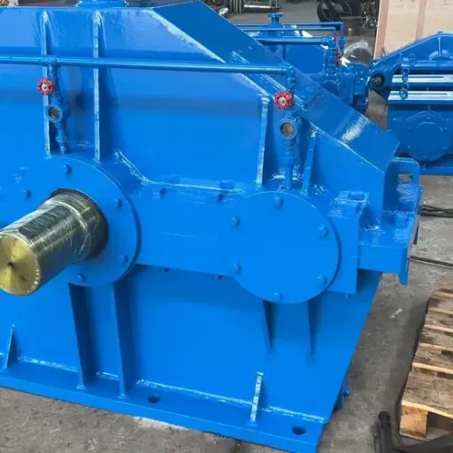
The reducer must fit the foundation and interface with the motor and pinion. Check:
Center height and base bolt pattern
Input shaft orientation and coupling type
Output shaft diameter, length, and keyway size
Clearance for maintenance access
Lubrication line and breather locations
For replacement projects, the easiest path is usually a dimensionally equivalent unit. For new mills, early coordination between the mill supplier and reducer manufacturer prevents costly redesign.
5. Specify Material and Heat Treatment
Edge drive ball mill reducers operate under severe loads. Quality indicators include:
Case-hardened alloy steel gears (HRC 58-62 typical)
Precision ground or shaved tooth profiles
Rigid cast iron or welded steel housing
Quality bearings sized for rated load and L10 life
Proper seals and breathers for dusty environments
Always ask your supplier for material certificates and heat treatment documentation. These details separate industrial-grade reducers from units that will not survive in a mill.
When Li Wei, a procurement manager at a cement plant in Southeast Asia, replaced a failed edge drive reducer, he requested material certificates and inspection reports from three suppliers. Only one supplier provided full documentation for gear hardness, tooth contact pattern, and bearing specifications. That reducer has now run for three years without abnormal vibration. The cheapest option, which lacked documentation, failed within 14 months.
MBY Series: The Standard Edge Drive Mill Reducer
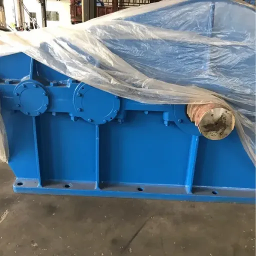
The MBY series is the most widely used edge drive mill reducer for ball mills and raw meal mills. As a dedicated MBY ball mill reducer, it is engineered specifically for the pinion-girth gear drive path used in edge-drive cement and mining mills.
Key Features of MBY Series Reducers
High torque capacity: Built to handle the continuous heavy loads of grinding mills.
Rigid housing: Minimizes deflection under load and maintains pinion mesh accuracy.
Case-hardened gears: Hardened tooth surfaces provide long wear life under abrasive dust and heavy media loads.
Output shaft for pinion coupling: Designed to interface with the mill pinion through a flexible or rigid coupling.
Reliable sealing: Protects bearings and gears from cement dust, moisture, and contaminants.
Common Applications
Cement raw meal mills
Cement finish mills
Coal mills
Slag mills
Mining ball mills with edge drive layout
The MBYX series is a related variant often used for similar applications with specific mounting or ratio requirements. Both series are proven in cement plants and mining operations worldwide.
At Jiangsu Manqi Machinery, we produce MBY, MBYX, and related mill reducer series from our facility in Taixing City. We also offer customized shaft arrangements, housing modifications, and special ratios when standard catalog models do not match the installation.
Need help matching an MBY reducer to your mill? Contact our engineering team with your motor power, drum speed, and mounting dimensions.
Material and Quality Indicators
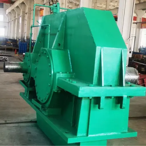
Not every reducer labeled for ball mill use can survive in a real mill environment. The following quality indicators help buyers distinguish industrial-grade units from lighter-duty alternatives.
Gear Materials and Hardness
Gears should be made from alloy steel and case-hardened to HRC 58-62. This hardness level resists pitting and wear from continuous meshing under high contact stress. The core of the gear should remain tough enough to absorb shock loads without cracking. Gear rating standards such as ISO 6336 and AGMA 2001 provide calculation methods for contact stress, bending stress, and durability.
Tooth Profile Accuracy
Precision-ground or shaved tooth profiles improve load distribution across the tooth face. Better load distribution reduces noise, vibration, and localized wear. It also improves efficiency by reducing sliding friction.
Housing Rigidity
A rigid housing maintains gear mesh alignment under load. Cast iron housings are common for smaller units. Welded steel housings are often used for larger, heavier reducers where weight and deflection control matter more.
Bearings and Lubrication
Bearings should be sized for the rated load and expected L10 life. For continuous-duty mills, lubrication must be reliable. Options include splash lubrication, forced lubrication, or oil-bath systems depending on mounting position and speed.
Inspection and Testing
Before shipment, a quality reducer manufacturer should perform:
Gear contact pattern inspection
Noise and vibration testing
Bearing temperature monitoring during run-in
Runout verification on input and output shafts
Oil leak testing on seals and joints
At Jiangsu Manqi Machinery, each reducer undergoes multi-stage quality inspection before it leaves our facility. We also provide drawings and test reports on request to support customer engineering and procurement documentation.
Installation and Maintenance Best Practices
Even a high-quality edge drive ball mill reducer will fail if it is misaligned, poorly lubricated, or operated beyond its rated conditions.
Alignment
Follow the supplier's alignment tolerances for the coupling between the reducer output shaft and the mill pinion. Misalignment causes uneven load distribution across the pinion and girth gear teeth, leading to accelerated wear and noise.
For older mills, check the foundation and mill shell for deflection or settlement before installing a replacement reducer. A new reducer cannot fix a distorted foundation. Concrete Construction publishes practical guidance on industrial concrete foundation inspection and maintenance that applies to mill installations.
Lubrication
Use the lubricant grade and viscosity recommended by the reducer manufacturer. In dusty cement plants, contamination control is critical. Keep breathers clean and check seals regularly.
Commissioning Checks
Before full-load operation, verify:
Correct oil level and oil cleanliness
Proper rotation direction
Coupling bolt torque
Vibration and noise baseline
Bearing temperatures during run-in
Record these baseline values. Future maintenance teams will use them to detect problems early.
Preventive Maintenance
A simple preventive schedule extends reducer life:
Check oil level and condition monthly
Inspect seals and breathers quarterly
Measure vibration and bearing temperature quarterly
Schedule oil analysis annually
Inspect tooth contact pattern during major shutdowns
When the maintenance team at a mining operation in Africa started recording vibration baselines on their edge drive reducer, they caught a bearing issue six months before it would have caused a failure. A scheduled replacement during a planned shutdown cost a fraction of what an emergency repair would have been.
When to Choose a Custom Edge Drive Reducer
Standard MBY series reducers cover many common mill sizes. However, some applications require a custom or non-standard edge drive reducer.
Situations That Call for Custom Design
The mill footprint differs from standard designs
Shaft orientation, center height, or bolt pattern is unique
Required torque exceeds catalog ratings
The installation has tight space or maintenance access constraints
Ambient conditions include high dust, temperature, humidity, or corrosive atmosphere
You are retrofitting a reducer into an older mill with non-standard interfaces
Custom Design Process
A reputable reducer manufacturer will review your drawings, operating conditions, and performance requirements before proposing a design. At Jiangsu Manqi Machinery, our R&D team evaluates feasibility, produces dimensional drawings for approval, and manufactures only after the customer confirms the design.
This process reduces the risk of interface mismatches and ensures the reducer fits both mechanically and operationally.
Have a non-standard mill layout? Request a custom reducer consultation and our engineers will review your drawings and operating conditions.
Frequently Asked Questions
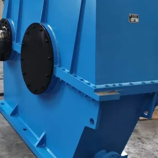
What reducer is used for edge drive ball mills?
The MBY series is the standard edge drive mill reducer for ball mills, raw meal mills, and coal mills. The MBYX series is a related variant used for specific mounting or ratio requirements.
How do I select the right edge drive ball mill reducer?
Start with motor power, input speed, required output torque, and service factor. Then confirm the reduction ratio, mounting dimensions, and material specifications. Always match the reducer to your actual operating conditions, not just the motor nameplate.
What is the typical service factor for a ball mill reducer?
Service factors for ball mill reducers typically range from 1.5 to 2.5, depending on mill size, media load, material hardness, operating hours, and startup frequency.
Can I replace an edge drive reducer with a center drive reducer?
Usually not without major mill modifications. The drive arrangement is determined by the mill design and foundation. For replacement projects, match the original layout unless the mill itself is being rebuilt.
What makes an industrial-grade edge drive reducer different from a standard gearbox?
Industrial-grade mill reducers use case-hardened alloy steel gears, rigid housings, heavy-duty bearings, and seals designed for dusty environments. They also undergo inspection and testing procedures that light-duty gearboxes do not.
Can Jiangsu Manqi Machinery produce custom edge drive reducers?
Yes. We design and manufacture custom and non-standard edge drive reducers based on customer drawings and operating conditions. Our engineering team provides drawings for approval before production begins.
Conclusion
An edge drive ball mill reducer is a critical component in cement plants, mining operations, and raw material grinding systems. Selecting the right unit means understanding your drive arrangement, calculating real torque and service factor requirements, and choosing a reducer built for continuous heavy-duty operation.
For edge-drive layouts, the MBY series remains the industry-standard choice. When standard dimensions or loads do not fit, a custom reducer engineered to your drawings and conditions is the safer path.
At Jiangsu Manqi Machinery, we manufacture MBY, MBYX, JDX, ZD, and custom ball mill reducers from our facility in Taixing City, one of China's leading gear reducer manufacturing hubs. Whether you are specifying a reducer for a new mill or replacing an existing unit, our engineering team can recommend the right standard or custom solution.
Ready to select your edge drive ball mill reducer? Contact our engineering team with your mill parameters, and we will provide a technical recommendation and quotation.
Recently Posted
-
NGW Planetary Gear Reducer: A Selection Guide for Compact High-Torque Drives
July 30, 2026An NGW planetary gear reducer is a single-stage epicyclic gearbox that uses a central sun gear, planet gears, and an internal ring Read More
 -
Heavy Duty Planetary Reducer: A Guide for High-Torque Industrial Drives
July 30, 2026A heavy duty planetary reducer is the right choice when you need high output torque, shock-load capacity, and a compact footprint Read More
 -
Planetary Gear Motor: A Complete Engineer's Guide to Selection and Application
July 30, 2026A planetary gear motor is a compact drive solution that pairs a planetary gear reducer with an electric motor to deliver high outp Read More
 -
High Torque Planetary Reducer: A Selection Guide for Heavy-Duty Industrial Drives
July 30, 2026A high torque planetary reducer is a compact drive system that distributes heavy loads across multiple planet gears meshing with a Read More

Contact Us
Recommended Products
-
 Kf127 Series Helical-Bevel Gear Motors for Industrial Power TransmissionNegotiableMOQ: 1 Set
 -
H1SH11 Modular Gearbox for Coal Mining Machinery With Cast Steel Housing and Mill Test ReportNegotiableMOQ: 1 Set
-
NGW101 Planetary Gear Reducer With Integral Flange Mount, 40Nm TorqueNegotiableMOQ: 1 Piece
-
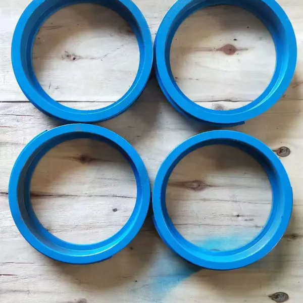
Shanghai Dongfang DFSS400-520/4 Industrial Centrifugal Pump Wear RingNegotiableMOQ: 10 Pieces
-
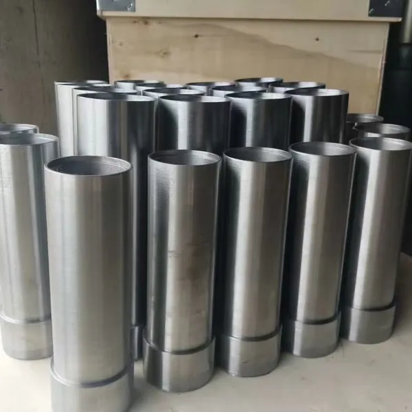
SLOW300-550 High Hardness Shaft Bushing Spare Parts Matching Shanghai Liancheng Water Pump AccessoriesNegotiableMOQ: 1 Piece
-
Shanghai Kaiquan KQSN300-X13A/390 Original Pump Seal Ring Spare PartNegotiableMOQ: 10 Pieces
-
Shanghai Dongfang IHH100-65-250 Chemical Pump Anti-Corrosion Seal RingNegotiableMOQ: 10 Pieces
-
Shanghai Dongfang DFSS600-24N/6 Wear Spare Ring for DFSS Water PumpNegotiableMOQ: 10 Pieces
-
Coaxial Parallel Shaft Gearbox Systems With Right Angle Spiral Bevel Helical Gear MotorsNegotiableMOQ: 1 Set
-
ZS125 Cylindrical Gear Reducer for Industrial Mixing ApplicationsNegotiableMOQ: 100 Sets
-
ZLY224 Cylindrical Gear Reducer With Hardened Steel Gears and 224mm Center DistanceNegotiableMOQ: 1 Piece
-
R87 Compact Inline Gear Motor Low Noise for Conveyor EquipmentNegotiableMOQ: 1 Set
-
NGW93 High Efficiency Low Vibration Planetary Gear Reducer For Machinery DriveNegotiableMOQ: 1 Piece
-
H1SH11 Modular Gear Reducers for CNC Machine IntegrationNegotiableMOQ: 1 Set
-
Gearmotor Converter System R/F/K/S Series Coaxial Parallel Shaft Gearbox Spiral Bevel MotorNegotiableMOQ: 1 Set
-
G3 Series Flange Mounted Helical Gear Motor Speed Reducer With Bevel GearboxNegotiableMOQ: 1 Set
-
Industrial Mixer Drive Solution With F Series Parallel Shaft Geared Motors F57 to F97NegotiableMOQ: 1 Set
-
Parallel Shaft Speed Reducer F Series, Models F57 F67 F77 F87 F97, IP55 Protection RatedNegotiableMOQ: 1 Set
-
Parallel Shaft Geared Motor F Series, F57-F97 With C-face Input Flange, 220V/380V OptionsNegotiableMOQ: 1 Set
-
Industrial ZSY630 Cylindrical Gear Reducer For Industrial Transmission EquipmentNegotiableMOQ: 1 Piece